|
 |
Description |
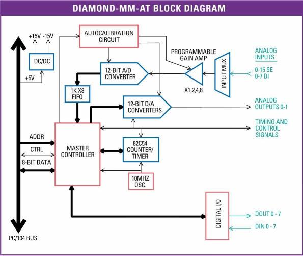
The Diamond-MM-AT analog I/O module offers autocalibration, programmable gain, A/D FIFO, and extended temperature operation to mid-range 12-bit analog I/O users.
 |
Block Diagram |
 |
Analog Inputs |
The 16 12-bit analog input channels feature programmable gains of 1, 2, 4,
and 8, as well as programmable unipolar/bipolar range, for a total of 9 different input ranges. Maximum sampling rate is 100KHz (total for all channels), and a 512-sample FIFO enables the board to operate at full speed in Windows and Linux operating systems using interrupts.
| Input Range |
Resolution |
| 0 - 10V |
2.44mV |
| 0 - 5V |
1.22mV |
| 0 - 2.5V |
0.61mV |
| 0 - 1.25V |
0.31mV |
| ±10V |
4.88mV |
| ±5V |
2.44mV |
| ±2.5V |
1.22mV |
| ±1.25V |
0.61mV |
| ±0.625V |
0.31mV |
 |
Analog Outputs |
The board also has 2 12-bit analog outputs with multiple unipolar and bipolar output ranges. A new programmable output range feature lets you set the output range anywhere between 0V and 10V with 1mV precision in software.
 |
Autocalibration |
Both analog inputs and outputs benefit from our unique multi-range autocalibration process. Multiple on-board precision references are used to calibrate the board in each range, thereby ensuring the highest degree of accuracy. The analog outputs are also fed back to the autocalibration circuit for precise output range calibration as well as user-programmable output ranges.
 |
Counters and Digital I/O |
The board also has an on-board counter/timer to control A/D sampling or rate generator functions, 8 digital inputs, and 8 digital outputs. New features enable you to generate hardware interrupts from the counter/timer as well as an external digital signal. And in keeping with our real-world-friendly design, Diamond-MM-AT requires only +5V power supply and operates over the full industrial temperature range of -40 to +85oC.
 |
I/O Header Pinout |
Diamond-MM-AT's 50-pin I/O header provides access to all I/O features of the board. Cable part no. C-50-18 can be used with this connector.
| Vin 15 / 7- |
1 |
2 |
Vin 7 / 7+ |
| Vin 14 / 6- |
3 |
4 |
Vin 6 / 6+ |
| Vin 13 / 5- |
5 |
6 |
Vin 5 / 5+ |
| Vin 12 / 4- |
7 |
8 |
Vin 4 / 4+ |
| Vin 11 / 3- |
9 |
10 |
Vin 3 / 3+ |
| Vin 10 / 2- |
11 |
12 |
Vin 2 / 2+ |
| Vin 9 / 1- |
13 |
14 |
Vin 1 / 1+ |
| Vin 8 / 0- |
15 |
16 |
Vin 0 / 0+ |
| Analog Ground |
17 |
18 |
VRef Out |
| Analog Ground |
19 |
20 |
Vout 0 |
| Analog Ground |
21 |
22 |
Vout 1 |
| Analog Ground |
23 |
24 |
+15V |
| -15V Output |
25 |
26 |
VRef In 0 |
| Analog Ground |
27 |
28 |
VRef In 1 |
| In 0- |
29 |
30 |
Digital Ground |
| Out |
31 |
32 |
Out 2 |
| Digital Out 7 |
33 |
34 |
Digital Out 6 |
| Digital Out 5 |
35 |
36 |
Digital Out 4 |
| Digital Out 3 |
37 |
38 |
Digital Out 2 |
| Digital Out 1 |
39 |
40 |
Digital Out 0 |
| Digital In 7 |
41 |
42 |
Digital In 6 |
| Digital In 5 |
43 |
44 |
Digital In 4 |
| Digital In 3 |
45 |
46 |
Digital In 2/Gate 0 |
| Digital In 1 |
47 |
48 |
Digital In 0/Gate 1/2 |
| +5V |
49 |
50 |
Digital Ground |
 |
Specifications |
| Analog Inputs |
| Number of inputs |
8 differential or 16 single-ended (user selectable) |
| A/D resolution |
12 bits (1/4096 of full scale) |
| Bipolar ranges |
±10V, ±5V, ±2.5V, ±1.25V, ±0.625V |
| Unipolar ranges |
0-10V, 0-5V, 0-2.5V, 0-1.25V |
| Input bias current |
3nA max |
| Max. input voltage |
±10V for linear operation |
| Overvoltage protection |
±35V on any analog input |
| Input Impedance |
10^13 ohms |
| Conversion rate |
100,000 samples per second with interrupts |
| Input FIFO |
512 samples, interrupt on half-full |
| Analog Outputs |
| Number of outputs |
2 |
| D/A resolution |
12 bits (1/4096 of full scale) |
| Output ranges |
Fixed: ±5V, 0-5V
Programmable: anywhere between 0V and 10V in 1mV increments |
| Output current |
±5mA max per channel |
| Settling time |
4µS max to ±2/2 LSB |
| Relative accuracy |
±1 LSB |
| Nonlinearity |
±1 LSB, monotonic |
| Reset |
All channels reset to OV |
| Digital I/O |
| Number of inputs |
8, HCT/TTL compatible |
| Input voltage |
|
| Logic 0: |
0.0V min, 0.8V max |
| Logic 1: |
2.0V min, 5.0V max |
| Input current |
±1µA max |
| Number of outputs |
8, HCT/TTL compatible |
| Output voltage |
|
| Logic 0: |
0.0V min, 0.33V max |
| Logic 1: |
3.8V min, 5.0 max |
| Output current |
|
| Logic 0: |
64mA max per line |
| Logic 1: |
-15mA max per line |
| Counter/Timers |
| A/D Pacer clock |
32-bit down counter (2 82C54 counters cascaded) |
| Clock source |
10MHz on-board source or external signal |
| General purpose |
16-bit down counter (1 82C54 counter) |
| Interrupt trigger |
End of A/D conversion or scan |
| General |
| Calibration |
A/D and D/A circuits calibrated under software control |
| Power supply |
+5VD±10%@350mA typical |
| ±15V output current |
±10mA max with DACs unloaded |
| Operating temperature |
-40°C to +85°C Extended |
| Weight |
3.3oz/93 |
| RoHS |
Compliant |
|


